This is a sandbox demo. It is intended to help you explore a specific TwikBot concept in isolation, using a pre-built product graph you can inspect and experiment with freely.
Overview
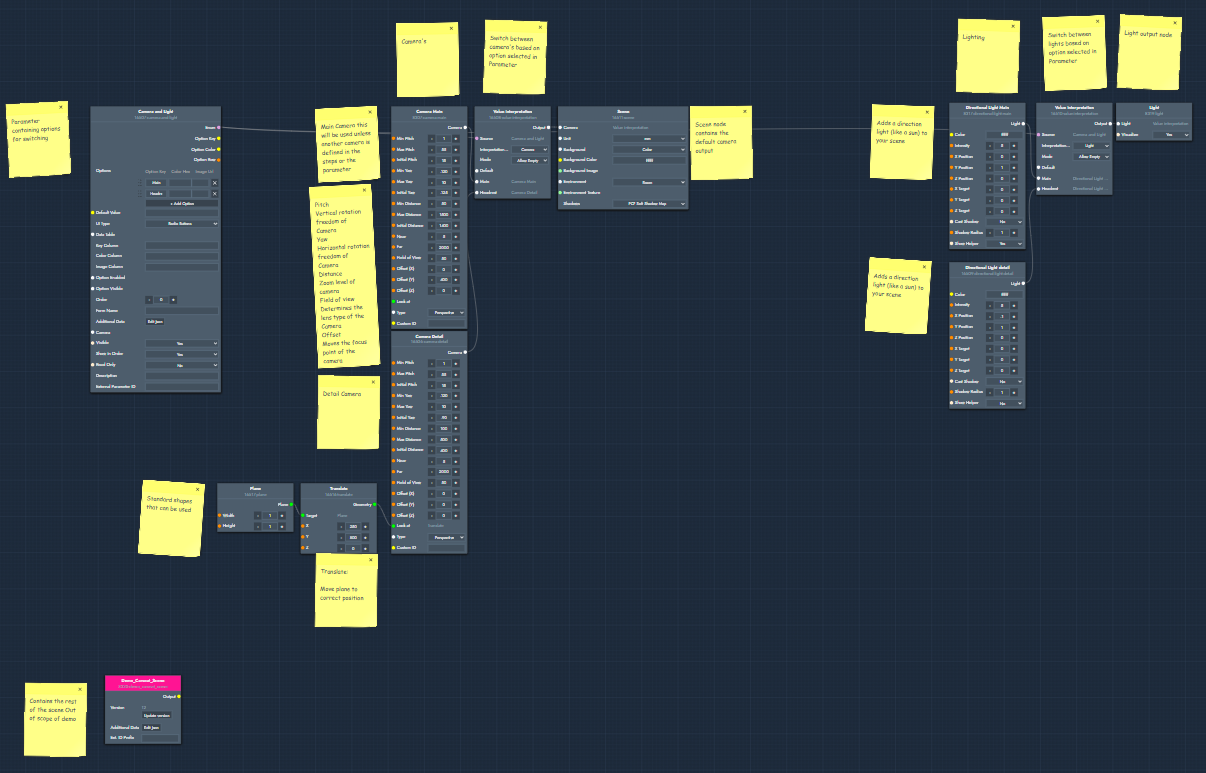
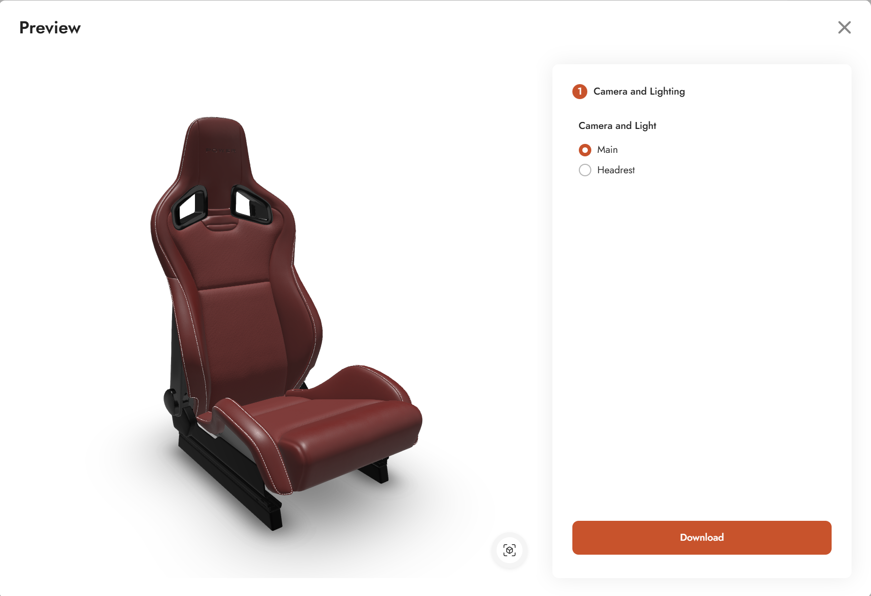
Camera and Lighting Basic - Demo shows how to set up switchable camera positions and directional lighting in TwikBot. The demo uses a racing seat as its subject, with two selectable views: a main view showing the full seat, and a detail view focused on the headrest.
The configurator consists of a single step (Camera and Lighting) with a radio button selector. Switching between the two options moves both the camera and the lighting to a preset matching that view.
Product graph
The graph file for this demo can be downloaded and imported directly into TwikBot Create.
Nodes used
|
Node |
Reference |
Purpose |
|---|---|---|
|
Option List — Camera and Light |
The UI element exposing the two view options (Main and Headrest) to the end user as a radio button selector. |
|
|
Camera node (Main) |
Defines the main camera position, pitch, yaw, distance, field of view, and offset for the full-seat view. |
|
|
Camera node (Detail) |
Defines the detail camera position for the headrest view. Uses a target geometry in the Look At input to set the focus point. |
|
|
Value Interpretation (camera) |
Switches between the two camera nodes based on the selected option in the Option List. |
|
|
Directional Light (Main) |
A sun-like light pointing toward the center of the scene, configured for the main view. Controls position, intensity, and color. |
|
|
Directional Light (Detail) |
A separate directional light configured for the headrest detail view. |
|
|
Value Interpretation (light) |
Switches between the two directional light nodes based on the selected option in the Option List. |
|
|
Plane |
A flat surface used as a floor or backdrop in the scene. |
|
|
Translate |
Positions the plane correctly in the scene. |
|
|
Light Output |
Makes the active light visible in the 3D scene of the visualizer. |
|
|
Scene Output |
The main scene output. Receives the active camera and can also accept environment images, HDRI lighting, or a background color. |
Graph explained
This graph shows how to wire up switchable cameras and lights using an Option List and Value Interpretation nodes. Follow the steps below to understand the data flow.
-
Option List (Camera and Light)
Start with an Option List parameter node. This drives the UI selector in the configurator sidebar. Two options are added: Main and Headrest. The selected option is used later by the Value Interpretation nodes to route the correct camera and light. -
Camera nodes
Add two Camera nodes, one for each view. On each camera you can configure pitch (vertical freedom), yaw (horizontal freedom), distance (zoom level), and field of view (lens type, from narrow to fisheye). The offset inputs let you shift the focus centerpoint away from the default center of the scene. For the detail camera, connect a target geometry to the Look At input to automatically set the focus point to that object rather than using a manual offset. -
Value Interpretation (camera)
Add a Value Interpretation node and connect both camera nodes to it. This node reads the selected option from the Option List and outputs the corresponding camera. Connect its output to the camera input of the Scene Output node. -
Scene Output
Add a Scene Output node. This is the main output for everything related to the scene environment. Connect the active camera from the Value Interpretation node here. The Scene Output also accepts environment images, HDRI for image-based lighting, and background color settings. -
Directional Light nodes
Add two Directional Light nodes, one per view. Directional lights behave like a sun: they always point toward the center of the scene by default. On each light you can adjust the position, the aim point, intensity, and color. Spotlights and point lights are also available as alternatives if the scene requires more control. -
Value Interpretation (light)
Add a second Value Interpretation node and connect both directional light nodes to it. This node reads the same selected option from the Option List and outputs the matching light. -
Light Output
Add a Light Output node and connect the active light from the Value Interpretation node to it. This makes the light visible and active in the 3D viewer. -
Plane and Translate
Add a Plane primitive and a Translate node to position it correctly in the scene. This provides a floor surface beneath the racing seat geometry.